Here’s a clear breakdown of the common laptop motherboard power supply structure, based on standard design patterns across most OEM boards like ASUS, HP, Lenovo, and Dell:
🔋 Common Laptop Motherboard Power Supply Structure
🔹 1. DC-IN Section
- Source: External adapter (usually 19V)
- Components:
- DC jack
- Protection MOSFETs (high-side and low-side)
- Current sense resistors
- Reverse polarity protection
- Function: Accepts and filters incoming power, protects against overcurrent and reverse polarity.
🔹 2. Battery Charging & Switching Circuit
- ICs: Battery charger IC (e.g., BQ24780S, ISL series)
- Function:
- Manages charging of Li-ion battery pack
- Switches between adapter and battery power
- Communicates with EC (Embedded Controller) for charge status
🔹 3. Main Power Rails
| Rail | Voltage | Purpose |
|---|---|---|
| +VCORE | 0.8V–1.2V | CPU core power |
| +VCCSA / +VCCIO | ~1.05V | System Agent / I/O |
| +VCCGT | ~1.0V | Integrated GPU |
| +1.8V | 1.8V | RAM, sensors, EC |
| +3VALW | 3.3V | Always-on rail (EC, power button) |
| +5VALW | 5V | USB, audio, display logic |
| +VDDQ | 1.2V / 1.35V | DDR memory voltage |
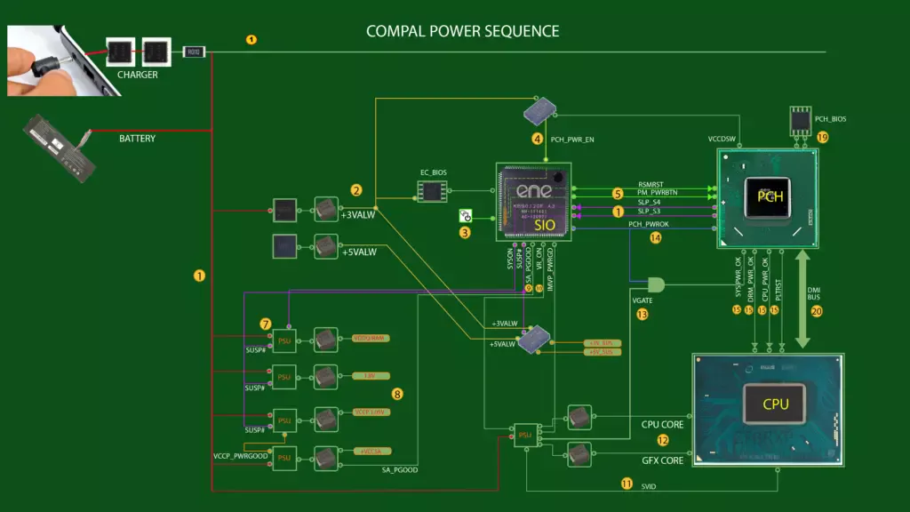
🔹 4. Power Sequencing Logic
- Controlled by: EC (Embedded Controller)
- Sequence:
- +3VALW and +5VALW power up first (standby)
- EC checks power button press
- EC enables main rails in order: VCCIO → VCORE → VCCGT
- Signals like
SUS_ON,SLP_S3,SLP_S5coordinate sleep/wake states
🔹 5. Voltage Regulation Modules (VRMs)
- Components:
- Buck converters (PWM controller + MOSFETs + inductors)
- LDOs (Low Dropout Regulators)
- Function: Step down 19V to usable voltages for CPU, GPU, RAM, etc.
🔹 6. Protection & Monitoring
- Includes:
- Thermal sensors
- Overvoltage/undervoltage protection
- Current monitoring ICs
- Purpose: Prevent damage, enable safe shutdown, report faults to EC/BIOS
🧠 Technician Notes
- Use schematics to trace power rails from DC-IN to CPU VCORE.
- Always check +3VALW and +5VALW first during no-power diagnosis.
- Power-good signals (
PG,VR_READY) are critical for boot sequencing.
